The person who calculated a tank battery’s emissions is no longer the only one checking them. In Colorado’s statewide study, a measurement-informed model plus reported maintenance, 38,936 t/y of methane, came to 1.47 times the modeled facilities’ 26,415 t/y inventory [1]. The Texas Commission on Environmental Quality (TCEQ), the state’s air permitting agency, lists four older flash methods as removed in its September 2025 guidance [2]. A number built on a struck method, or blind to equipment failures, is a number someone else can challenge.
A storage tank emissions calculation is the yearly estimate of the gas a crude oil or condensate tank releases to the air. AP-42 Chapter 7.1, Organic Liquid Storage Tanks, is the relevant section of the emission factor compilation published by the Environmental Protection Agency (EPA) [3]. EPA is the federal agency whose stated mission is to protect human health and the environment [4]. The calculation has to account for three separate mechanisms: two evaporative, and flashing, which is not [3].
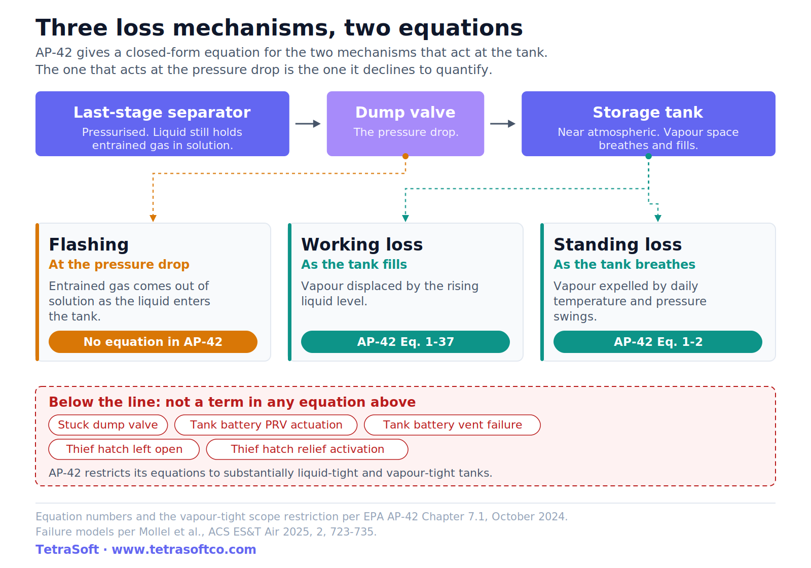
Standing loss is vapor pushed out as the tank breathes with daily temperature and pressure swings [3]. Working loss is vapor displaced when liquid is pumped in [3]. Flashing is different, because it is entrained gas coming out of solution when pressurized liquid drops to tank pressure [3]. For a production tank battery taking liquid from a separator, flashing is the mechanism the standard reference declines to give you an equation for [3].
The three loss mechanisms a tank calculation has to cover come first, with AP-42’s equations and the flash methods state agencies accept. The post then shows where the standard approach breaks and what a failure-inclusive estimate changes. Five common questions close the post, from what flash emissions are to federal reporting changes. The target readers are engineers, environmental staff and consultants who calculate or defend a tank battery’s emissions.
Quick Answer: For a fixed roof tank, routine loss is standing plus working loss, and EPA AP-42 Chapter 7.1 gives an equation for each [3]. Flashing loss, a third mechanism at tanks fed pressurized liquid from a separator, gets no estimation method in that section [3]. Equipment failures such as a stuck dump valve sit outside all three mechanisms and can add to the total. A failure-inclusive Monte Carlo estimate produces a distribution rather than one number.
The Three Loss Mechanisms a Tank Calculation Has to Cover
Total routine loss from a fixed roof tank is the sum of just two terms [3]. AP-42 Equation 1-1 states it as total losses equal standing losses plus working losses, both in pounds per year [3]. Everything difficult about an upstream tank sits outside that sum.
| AP-42 equation | Formula |
|---|---|
| Eq. 1-1, total routine loss | LT = LS + LW |
| Eq. 1-2, standing loss | LS = 365 × VV × WV × KE × KS |
| Eq. 1-37, working loss | LW = VQ × KN × KP × WV × KB |
| Symbol | Meaning | Units |
|---|---|---|
| LT | Total routine losses | lb/yr |
| LS | Standing loss (vapor breathed out as the tank warms and cools) | lb/yr |
| LW | Working loss (vapor displaced as liquid is pumped in) | lb/yr |
| VV | Tank vapor space volume | ft³ |
| WV | Stock vapor density | lb/ft³ |
| KE | Vapor space expansion factor | per day |
| KS | Vented vapor saturation factor | dimensionless |
| VQ | Net working loss throughput | ft³/yr |
| KN | Working loss turnover (saturation) factor | dimensionless |
| KP | Working loss product factor (0.75 for crude oils, 1 otherwise) | dimensionless |
| KB | Vent setting correction factor (1 for open vents and settings within ±0.03 psig) | dimensionless |
Neither equation contains a flashing term, which is the whole difficulty with an upstream tank. The word routine in that equation is AP-42’s own label for standing plus working losses [3]. AP-42 restricts that usage to itself, noting it does not carry over to permitting purposes such as New Source Review [3].
AP-42 leaves flashing out of the sum as beyond the section’s scope, not because it is abnormal: it is typical of production tanks [3]. AP-42 describes it as occurring in addition to routine standing and working losses [3].
OGMP 2.0, the Oil and Gas Methane Partnership, is the United Nations Environment Programme’s flagship oil and gas reporting and mitigation programme [5]. Its guidance on unstabilized liquid storage tanks identifies flash losses as the most significant of the three for tanks fed from a higher-pressure separator [6]. The mechanism OGMP calls most significant is therefore the one the standard reference leaves without an equation.
Standing loss, Equation 1-2, is built from the tank vapor space volume and the stock vapor density [3]. It also carries a vapor space expansion factor and a vented vapor saturation factor, multiplied by 365 days [3]. Working loss, Equation 1-37, is built from net throughput and a turnover saturation factor, together with a product factor and a vent setting correction [3]. Both use tank, stock and weather inputs; AP-42 excludes gas-injected tanks, unstable or boiling stocks, and vapor pressures unknown or not readily predictable.
The covered mechanisms and flashing differ in what drives them, not where they act: all three occur at the tank. AP-42 describes pressurized separator liquid experiencing a pressure drop upon entering the storage tank [3]. Refining an input to Equations 1-2 or 1-37 cannot recover flashing, which depends on last-stage separator conditions neither equation takes. Failures sit outside all three, such as a pressure relief valve (PRV) actuating, which vents the tank when pressure passes a threshold [7].
What Drives Each Mechanism
Each mechanism has its own driver: weather swings drive standing loss, filling drives working loss, and the separator-to-tank pressure drop drives flashing [6]. In the OGMP 2.0 guidance, working losses occur when rising liquid levels and agitation push out the vapors above the liquid surface [6]. Standing losses occur when vapors expand and vent with daily and seasonal temperature and barometric pressure changes [6].
The guidance names what the vapor volume depends on, including tank roof configuration, capacity, throughput and separator pressure [6]. The flashed volume scales with the pressure differential between the separator and the tank [6].
The guidance gives 35 to 50 psig as a typical separator pressure, and its example figure shows one separator at 40 psig [6]. Real batteries vary: liquid may pass through one or more separators, and AP-42 ties flashing to the last stage separator’s exit pressure [3]. The same tank behind a higher-pressure separator is a different emissions problem.
The American Petroleum Institute (API) represents all segments of America’s natural gas and oil industry [8]. API gravity is its scale, in degrees, for the density of crude oil or condensate [9]. Lighter crude flashes more than heavy, with API gravity above 36 degrees named as the dividing line [6].
Tanks with frequent cycling and high throughput have more working losses than low-throughput tanks that hold oil longer [6]. An operator wanting their battery’s split can derive it from site data such as separator pressure, liquid properties, throughput and tank configuration.
The practical consequence is uncomfortable. Refining a standing loss calculation leaves untouched the flash term, which the guidance calls the most significant.
Flashing Is the Term AP-42 Leaves to You
AP-42 defines flashing in a short section of its own but puts methods for estimating it beyond the section’s scope [3]. AP-42 compares flashing to “carbon dioxide fizzing out of solution when a carbonated beverage container is opened.” [3] The section names crude oil and condensate storage in the production field as the most common case [3]. The last stage separator’s exit pressure can be well above the first storage tank’s, so remaining gases can flash out of solution there [3].
Then AP-42 stops. It states that numerous methodologies exist but that discussion of them is beyond the scope of the section [3]. Chapter 7.1’s note on accuracy mentions two kinds: methods relying on a site-specific sample and methods relying on process simulation [3]. The same section specifies where to characterize the fluid, which is the last stage separator, in the oil compartment before the dump valve [3].
AP-42 names process simulation as one method family, and warns its accuracy depends on how representative the modeling assumptions are [3]. Flashing is a phase-equilibrium process that equation-of-state software can compute, though the guidance also accepts empirical correlations. Given separator pressure and temperature, liquid composition, flow rate and ambient conditions, an equation-of-state calculation yields the flashed volume and composition.
The gap for an operator is the flash calculation and the failure modes around it.
TetraSoft MAES, our physics-based emissions estimation platform, closes part of that gap for methane by simulating the instantaneous flash inside the whole battery. The 2023 CSU thesis describing the simulator says it models instantaneous flash, not working flash [10]. The name stands for Mechanistic Air Emissions Simulator [11].
For its major equipment units, the model ties emissions to the fluids moving through the equipment and its operating state, including key failure modes [10]. Failures that no AP-42 equation contains, such as stuck dump valves and thief hatch failures, are modeled too [11].
Coupled-equipment modeling links the separator, the dump valve and the tank, though non-mechanistic emitters still draw from emission and activity factor distributions [10]. The flash calculation and the failure models therefore run against the same fluid and operating conditions [7]. The 2023 thesis estimates wellhead composition from a University of Texas database, using inputs such as GOR and API gravity, then computes flash per stage [10].
The flash and failure models run on TetraSoft’s MAES Platform, with the separator, the tank and its controls in one model [11].
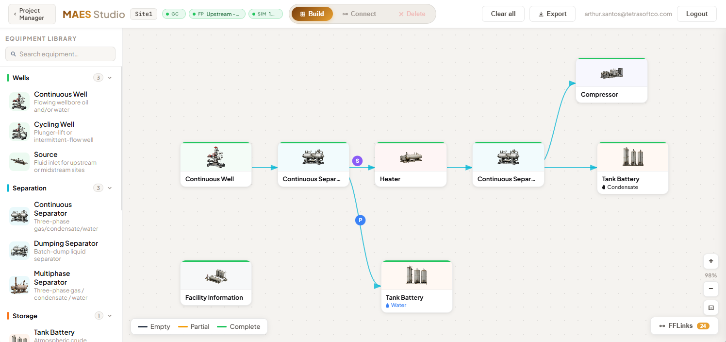
Its equipment library also covers wells, separators, heaters, compressors, flares, dehydrators, vapor recovery units and pneumatic devices [11].
The result is a distribution rather than a single number, given as a P5, a mean and a P95 [11]. P5 and P95 are the 5th and 95th percentiles, the values that 5 and 95 per cent of simulated outcomes fall below. The results break emission events down by failure mode [11].
That breakdown tells an operator which failure is driving the total. Flash is a design and control question, while a failure is a maintenance one somebody can go and fix.
What the Permitting Agencies Accept Instead
AP-42 declines to name a method, and the state permitting agencies filled the gap themselves. The Air Permits Division of the Texas Commission on Environmental Quality lists four in its flash emissions guidance, RG-622 [2]. Only one of them returns flash alone; the other three produce working and breathing losses in the same run [2]. E&P Tanks, named in the table below as V3.0 (version 3.0), is a program published by the American Petroleum Institute (API) [12].
| Method TCEQ accepts | What it returns | What it needs |
|---|---|---|
| Direct measurement of tank emissions | Working, breathing, and flash | All vapors routed to one point, with flow, temperature, and extended gas chromatography |
| Process simulator software | Working, breathing, and flash | A site-specific sample, plus the equipment arrangement and operating parameters |
| E&P Tanks V3.0, sampling option | Working, breathing, and flash | A pressurized liquid or gas sample from the separator |
| Laboratory gas-oil ratio (GOR: gas released per volume of liquid) from a pressurized sample | Flash only | A pressurized liquid sample flashed to tank conditions in a laboratory |
That is permitting guidance rather than rule text, and TCEQ describes its own accuracy ranking as a preliminary opinion [2]. Process simulation appears on the Texas, Kansas and Louisiana lists surveyed here, as does E&P Tanks.
The list is shorter than it used to be [2]. The September 2025 edition lists four methods as removed from the acceptable set, without saying when each was removed [2].
They are the Vasquez-Beggs equation and the equation known as EC/R [2]. They also include E&P Tanks’ earlier version 2.0 (V2.0) geographical database option, and the Griswold and Ambler GOR chart [2]. One of them, the EC/R equation, estimates how each component splits between liquid and vapor at tank pressure [13]. The stated grounds are that these are older methods no longer supported [2].
That removal matters because other states still use Vasquez-Beggs, the method the Kansas fact sheet leads with. The Kansas fact sheet names it the default method required for all facilities with flash emissions [13]. In Louisiana, it is accepted as an alternate method, approved case by case [12].
The Kansas sheet carries no revision date [13]. The Louisiana page is undated [12].
The Kansas sheet is candid about the equation it requires. The sheet records that tank-flashing estimates made with Vasquez-Beggs may be considerably underestimated or overestimated [13]. It attributes that spread to the numerous variables that affect flash losses [13].
The same caveat adds that the variability is more apparent near the wellhead, where the pressure drop is highest and liquid composition more variable [13]. Volatile organic compounds (VOC) are carbon compounds EPA regulates mainly because they form ground-level ozone in smog [14]. The sheet also notes that the equation returns total VOC only, without speciation, and does not calculate standing or working losses [13].
None of that settles which list is right. It does mean the applicable list has to be established before a method is chosen. The same calculation, performed the same way, is required in one jurisdiction and struck from the accepted set in another.
Where the Standard Approach Breaks
Every one of those equations describes a tank behaving as designed. AP-42 says so in its own scope note, restricting the equations to tanks that are substantially liquid-tight and vapor-tight [3]. A tank with a hatch propped open or a relief valve stuck open is not vapor-tight. AP-42 places such a tank outside its equations’ scope.
AP-42 places the sampling or modeling point at the last stage separator, before the dump valve [3]. AP-42 therefore characterizes the fluid at exactly the point whose failure its equations do not model.
That dump valve is a typical failure point, and when it sticks, high-pressure gas reaches tanks rated for low pressure. The 2023 CSU thesis on Colorado’s Denver-Julesburg (DJ) Basin chose that failure mode to show that even a single failure mode can affect emissions [10].
Five Failure Models Cover the Tank Battery
In the DJ Basin work, mechanistic modeling of a tank battery centres on a short list of major equipment failure modes [7]. The study names five for its analysis, and notes that more failure models are being added [7].
| Failure model | What happens |
|---|---|
| Stuck dump valve | Valve does not fully close, so a fraction of separator gas passes downstream to equipment not rated for it |
| Tank battery PRV actuation | Gas entering plus gas flashed exceeds a threshold, so the relief valve opens and vents until flow drops |
| Tank battery vent failure | The vent sticks open without any upstream stimulus, leaving the tank open to atmosphere until operators detect it |
| Tank thief hatch left open | The hatch is left open or pops open unprompted, leaving the tank open to atmosphere until detected |
| Thief hatch pressure relief activation | Tank over-pressure, as in PRV actuation, opens the hatch, which stays open until detected |
The stuck dump valve can start a chain, sending gas to the tanks that triggers over-pressure venting [7]. It sends high-pressure gas into atmospheric tanks rated for low pressure, and the over-pressure opens the tank relief valves [7]. The dump valve fails from deposit buildup, controller failure, or corrosion [7]. AP-42’s factors for other equipment, and what they assume, are covered in AP-42 Emission Factors: Gas Engines, Turbines, Boilers, Flares.
What a Failure-Inclusive Estimate Changes
One change is that the answer stops being one number [7]. A mechanistic simulator models the probability of a stuck dump valve and the fraction of gas lost when it sticks, then runs the facility repeatedly [7]. The output is a distribution of expected emission ranges [7].
Another change is timing [7]. Wells cycled on and off send varying fluid flows through the facility, driving varying gas loss from separators and emissions from tanks [7]. A large failure source can be brief bursts at much higher rate, separated by long periods with none [7]. That variability is what an annual factor cannot carry.
The Failure Also Changes What Comes Out
A stuck dump valve does more than increase the emission rate [7]. It shifts the composition, because leaner, methane-rich separator gas now escapes with the tank vapor.
The study’s current facility is a wellpad with three stages of separation [7]. Depending on facility configuration, the ethane-to-methane ratio could vary by 2.15 times [15].
Anyone reconciling against a measurement needs the composition, not just the rate. A basin-level aircraft survey that samples ethane alongside methane can help reveal the shift; methane-only plume imagers can size a plume, not the ratio [10]. The same logic drives the satellite comparisons described in Why Satellites Show About 2x More Methane Than Inventories.
Why the Study Tested One Failure Mode
The published DJ Basin work exercised one of the five [7]. The 2023 thesis chose the stuck dump valve to show that even a single failure mode can affect a facility’s emissions [10]. Failure frequency was set at once per year for each separator, against a once-in-127-years baseline, simulated over 365 days with 100 Monte Carlo iterations [10].
The simulator behind that work is the Mechanistic Air Emissions Simulator (MAES) [15].
The simulation engine was developed at Colorado State University and the University of Texas at Austin [11]. TetraSoft provides commercial access to it through a licence with Colorado State [11].
Frequently Asked Questions
What are flash emissions from a storage tank?
Flash emissions are gases that come out of solution when pressurized liquid enters a tank at lower pressure [3]. They are not an evaporative loss, which is what separates them from standing and working losses [3]. They occur only in tanks receiving pressurized liquid streams that still contain entrained gas [3]. That is typical of production tanks fed by a separator, and does not typically occur at downstream facilities [3].
Does AP-42 give an equation for flashing losses?
No [3]. AP-42 Chapter 7.1 defines flashing and devotes a section to it, then states that guidance for estimating it is beyond the scope of that section [3]. It notes instead that numerous methods exist, and that the accuracy of sample-based or simulation-based methods depends on how representative their inputs are [3]. It also notes that a tank with flashing potential still has to be evaluated for routine standing and working losses [3].
Why is my calculated tank number lower than a measured one?
One structural reason is that the calculation represents the tank operating as designed. Colorado’s statewide study built two independent models, the Mechanistic Air Emissions Simulator (MAES) and a statistical one, and both put emissions above the reported inventory [1]. The state air regulator, CDPHE, then set 2026 state default intensity verification factors for reported upstream methane: 2.2 Front Range, 2.7 West Slope, 2.5 elsewhere [16]. Measurement timing matters too, since a survey captures an instant while an inventory reports an annual average.
What data do I need to model a tank battery mechanistically?
You need the equipment list for the battery, including separation stages, tank count, and control devices. You also need throughput and equipment pressures and temperatures; the DJ Basin study found throughput raised emissions at older wellpads, not its tankless future design [15]. You need the crude oil or condensate properties at the last stage separator, in the oil compartment before the dump valve [3]. Failure rates and emission factors for the other equipment are also inputs, drawn from public data, published studies and partner operators [7].
Do tank emissions still have to be reported if the federal program changes?
State inventory programs such as Colorado’s rest on state rules, so their filing obligation survives a federal reporting change, though some reference federal methods. Colorado’s Oil and Natural Gas Annual Emission Inventory Reporting (ONGAEIR) is one example, with operators filing yearly inventories by June 30 [17]. Colorado ONGAEIR Due June 30: A Practical Filing Checklist walks through that filing cycle.
Subpart W is the petroleum and natural gas section of EPA’s Greenhouse Gas Reporting Program (GHGRP), which collects data from large emission sources [18]. The federal picture is less settled: EPA’s pending proposal would suspend most Subpart W reporting until 2034, but 2025 reports are due March 10, 2027.
Interested in building a Measurement-Informed Inventory for your operations? Contact us to learn about our MAES-based estimation services.
References
- Brown et al., Colorado Ongoing Basin Emissions (COBE) Updated Final Report, November 20, 2025. Colorado State University METEC and Colorado School of Mines, for the Colorado Department of Public Health and Environment. https://mountainscholar.org/items/c775f2b6-f239-4f0c-95fc-e591afbe4145
- TCEQ Regulatory Guidance RG-622, Calculating Volatile Organic Compounds (VOC) Flash Emissions from Crude Oil and Condensate Tanks at Oil and Gas Production Sites, revised September 2025. Texas Commission on Environmental Quality, Air Permits Division. https://www.tceq.texas.gov/assets/public/permitting/air/Guidance/NewSourceReview/guidance_flashemission.pdf
- EPA AP-42 Chapter 7.1, Organic Liquid Storage Tanks, June 2026. United States Environmental Protection Agency, Compilation of Air Pollutant Emission Factors. https://www.epa.gov/system/files/documents/2026-08/c7s1_2026.pdf
- EPA, Our Mission and What We Do. United States Environmental Protection Agency. https://www.epa.gov/aboutepa/our-mission-and-what-we-do
- OGMP 2.0, Oil and Gas Methane Partnership 2.0 homepage. United Nations Environment Programme. https://www.ogmpartnership.org/
- UNEP OGMP 2.0 Technical Guidance Document, Unstabilized Liquids Storage Tanks (SG Approved), posted April 2025. Oil and Gas Methane Partnership 2.0. https://www.ogmpartnership.org/sites/default/files/2025-04/Unstabilized-liquid-storage-tanks-TGD-SG-Approved.pdf
- Mollel et al., ACS ES&T Air 2025, 2, 723-735, DOI 10.1021/acsestair.4c00168. Using Prototypical Oil and Gas Sites to Model Methane Emissions in Colorado’s Denver-Julesburg Basin Using a Mechanistic Emission Estimation Tool. https://doi.org/10.1021/acsestair.4c00168
- API, About API. American Petroleum Institute. https://www.api.org/about
- EIA, Glossary, API Gravity. U.S. Energy Information Administration. https://www.eia.gov/tools/glossary/index.php?id=A
- Mollel, Colorado State University MS thesis, 2023. https://mountainscholar.org/bitstreams/b7703270-a6cd-43a2-8a0e-233170c87649/download
- TetraSoft, MAES Platform. https://tetrasoftco.com/maes-platform/maes-landing.html
- LDEQ, Flash Gas Calculation Methods. Louisiana Department of Environmental Quality, undated. https://www.deq.louisiana.gov/page/flash-gas-calculation-methods
- KDHE, Acceptable Methods for Calculating Flash Tank Emissions. Kansas Department of Health and Environment fact sheet, undated. https://www.kdhe.ks.gov/DocumentCenter/View/1093/Acceptable-Methods-for-Calculating-Flash-Tank-Emissions-PDF
- EPA, Technical Overview of Volatile Organic Compounds. United States Environmental Protection Agency. https://www.epa.gov/indoor-air-quality-iaq/technical-overview-volatile-organic-compounds
- CSU METEC, Using Prototypical Sites to Model Methane Emissions in Colorado’s Denver-Julesburg Basin Using the Mechanistic Air Emissions Simulator (MAES), project page. Colorado State University, Methane Emissions Technology Evaluation Center. https://metec.colostate.edu/mechanistic-air-emissions-simulator/
- Colorado Department of Public Health and Environment, Air Pollution Control Division, Oil and gas greenhouse gas intensity program: 2025 ONGAEIR workbooks due June 30, 2026 subject to the 2025 state default intensity verification factor of 1.164; 2026 factors of 2.2 (9-County Front Range), 2.7 (3-County West Slope) and 2.5 (Rest-of-State) for reporting year 2026 emissions due June 30, 2027. https://cdphe.colorado.gov/apcd-ghg-intensity-program. Accessed November 2026.
- CDPHE, Oil and Natural Gas Annual Emission Inventory Reporting. Colorado Department of Public Health and Environment. https://cdphe.colorado.gov/ongaeir
- EPA, Subpart W: Petroleum and Natural Gas Systems. United States Environmental Protection Agency, Greenhouse Gas Reporting Program. https://www.epa.gov/ghgreporting/subpart-w-petroleum-and-natural-gas-systems
This post is for informational purposes only and does not constitute legal or compliance advice. Consult qualified legal counsel or a compliance professional for guidance specific to your operations and jurisdiction.
Interactive tool
Which flash method does TCEQ accept for your tank?
Nothing leaves your browser. This reports what one document says. It is a starting point, not a permitting determination.
Method list, flowsheet options, and submission requirements from TCEQ Regulatory Guidance RG-622, Calculating Volatile Organic Compounds (VOC) Flash Emissions from Crude Oil and Condensate Tanks at Oil and Gas Production Sites, Air Permits Division, revised September 2025. Texas only. Other states publish their own lists and do not agree with this one: the Kansas fact sheet still makes Vasquez-Beggs its default, and Texas struck that method.
Interactive reference
Where the AP-42 inputs actually come from
Equations 1-2 and 1-37 look usable until you try to fill them in. This resolves every symbol against AP-42's own lookup tables and says which ones no table can give you. Note what is absent: separator pressure appears nowhere, which is why refining any value below cannot recover the flash.
Site values Tables 7.1-6 and 7.1-7
- TAX 63.5 °F
- Average daily maximum ambient temperature tabulated in °F; the equations take °R
- TAN 37.9 °F
- Average daily minimum ambient temperature tabulated in °F; the equations take °R
- ΔTA 25.6 °F
- Average daily ambient temperature range derived as TAX minus TAN; identical in °F and °R
- I 1491 Btu/ft²·day
- Average daily total solar insolation
- PA 12.08 psia
- Atmospheric pressure
- α 0.17 dimensionless
- Tank shell solar absorptance, white in good condition Table 7.1-6
Liquid values Table 7.1-2
- MV 50 lb/lb-mole
- Vapour molecular weight
- ML 207 lb/lb-mole
- Liquid molecular weight
- WL 7.1 lb/gal
- Liquid density
- PVA not tabulated
- True vapour pressure at 60 °F Figure 7.1-16
Every symbol in Equations 1-2 and 1-37 8 inputs
| Symbol | Supplied by | How you get it |
|---|---|---|
| VV Tank vapour space volume ft³ | Tank | From the tank itself: diameter, shell height, and average liquid depth. No table can supply it. |
| WV Stock vapour density lb/ft³ | Liquid + tank | Needs the vapour molecular weight above plus the true vapour pressure at the liquid surface temperature. AP-42 tabulates no vapour pressure for midcontinent crude oil, sending you to Figure 7.1-16. |
| KE Vapour space expansion factor per day | Weather | Built entirely from the six site values above: the 25.6 °F daily range at Denver, CO, the solar insolation, the atmospheric pressure, and the shell absorptance. Nothing about the liquid enters it. |
| KS Vented vapour saturation factor dimensionless | Liquid + tank | KS = 1 / (1 + 0.053 · PVA · HVO), so it needs the vapour pressure and the tank's vapour space outage. Both terms are positive, so it can never exceed 1. |
| VQ Net working loss throughput ft³/yr | Operations | The liquid actually pumped into the tank over the year, from the site record rather than any table. |
| KN Working loss turnover factor dimensionless | AP-42 rule | 1 Fixed for the tanks this post is about: where flashing occurs, AP-42 sets it to 1 regardless of the number of turnovers. |
| KP Working loss product factor dimensionless | AP-42 rule | 0.75 The value AP-42 sets for crude oils. |
| KB Vent setting correction factor dimensionless | AP-42 rule | 1 Applies to open vents and to vent settings up to ±0.03 psig. |
Two of the eight are not lookups at all. The tank's vapour space and the year's throughput come off the tank and the site record. Three are fixed by rule. Only the liquid properties and the weather come from a table, and AP-42's single crude oil entry sends you to a figure rather than publishing a vapour pressure. Where nothing is known about the tank's surface, AP-42's own default is a white shell and roof in good condition.
Values from EPA AP-42 Chapter 7.1, Organic Liquid Storage Tanks, October 2024, Tables 7.1-2, 7.1-6 and 7.1-7.
Comments
0Share your thoughts. All comments are moderated before appearing.
No comments yet. Be the first to share your thoughts!